146 Results
View results:
Sort by:

In RFEM, you have the option to create and analyze cables using sheaves. For this, use the "Cable on Pulleys" member type. It is ideal for pulley systems, where the longitudinal forces are transferred via sheaves.
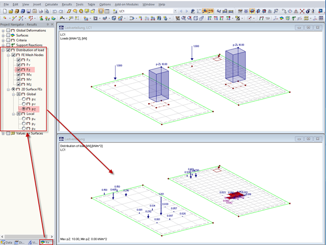
"Distribution of load" represents a load actually applied to the system of FE mesh points or FE surfaces. The FE mesh size plays an important role in the loading in the case of line loads and free loads in particular.
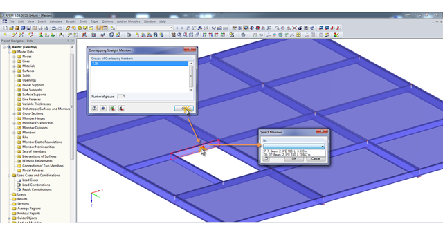
A modell check allows you to find overlapping members, among other things. However, this targeted selection could cause some minor problems. Therefore, there is a selection window now available, which appears when you click on one of the elements. This appears by clicking on one of the elements. Additional information helps you to select the correct member.
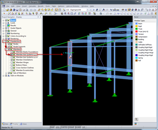
The local coordinate system of a member is particularly important when defining member end releases and member nonlinearities. The definitions follow the orientation of the axes. You can temporarily adjust the visibility of these member axes by means of preselection.
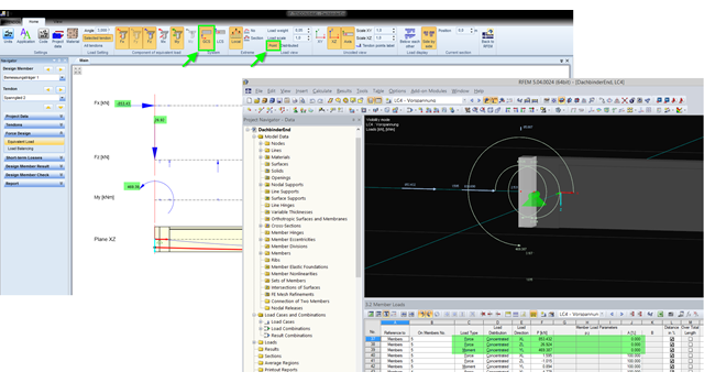
The equivalent loads determined in RF-TENDON due to prestress are transferred in RFEM as member loads or as line loads. A member load is used for member types with their own stiffness; a line load is used for member types without their own stiffness. In order to understand which values of the concentrated loads are to be transferred from RF‑TENDON to RFEM, you should use the following display settings: ~ Reference of the loads to the global coordinate system (GCS), ~ Load display: "Point"
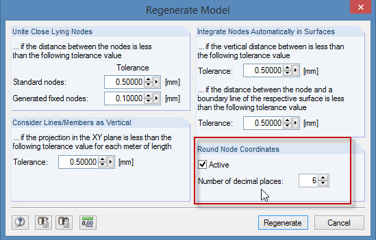
During the cooperation between the structural and design engineers, the DXF format is often used if there is no direct interface. However, the geometrical data of these DXF files are not always accurate. For example, an inaccuracy in the third decimal place is not noticeable, but it can lead to numerical problems when generating the FE mesh in RFEM.
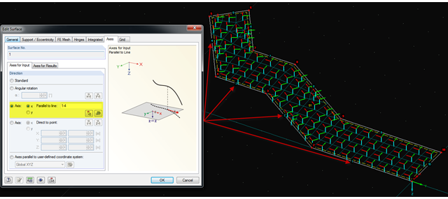
It is often necessary to adjust the FE mesh of surface elements to the geometric structure. RFEM provides various options for this. For example, the FE axis can be rotated around a point, aligned in the direction of a point, or oriented to a user-defined coordinate system. Another option is the direction parallel to a line, and in this case in particular, it is possible to enter or select several lines.
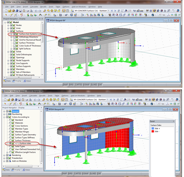
When calculating the surface reinforcement in RF-CONCRETE Surfaces, the result values for both surface sides +/- z are available. If you are unsure which side of a surface is the positive or the negative z side, you can hide the local coordinate system of each surface in the RFEM Project Navigator - Display under "Model" → "Surfaces" → "Surface Axis Systems x,y,z". In the case of complex structures, this can quickly become confusing. Displaying multiple axis systems makes it difficult to recognize the incorrect direction of a surface, for example (see the figure on the top).
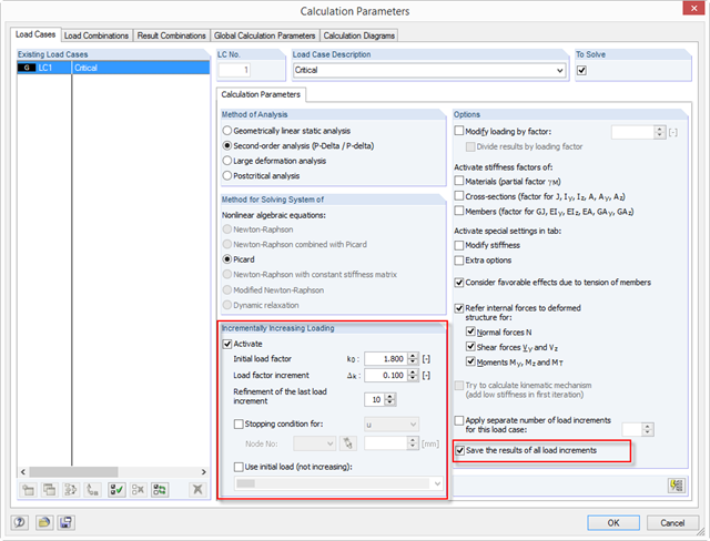
With RFEM 5.04, there are new options for the system analysis (critical load factors) of load cases and load combinations in the calculation parameters of the RF‑STABILITY add‑on module: ~ The load increment is not closed due to stability problems, but optionally also due to predetermined deformation limits. ~ The calculation method is applicable to all nonlinear calculations. ~ You can define an initial load (LC/CO) that is not increased (for example, self-weight). ~ The "Refinement of the last load increment" option provides an efficient option to determine the critical load factor as precisely as possible.
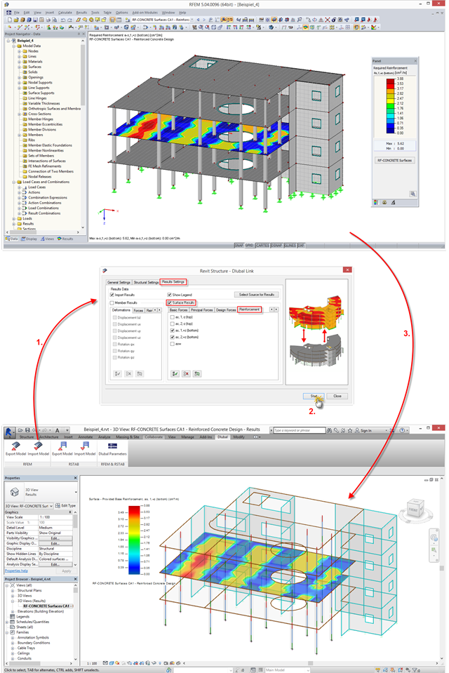
The interface between RFEM/RSTAB and Autodesk Revit has been improved: You can now transfer results from RFEM/RSTAB to Revit and display them there graphically. This option is available in a new tab when importing a file.